So I've ultimately ended up with the situation where I have two JAMMA harnesses, one each for Out Run and Power Drift. Both harnesses connect easily to a Power Drift control panel and pedals. I also have a set of pedals for use on old Windows (95/98 etc.) systems. I simply cut off the 15-pin connector and wired it directly to my Out Run harness; since getting the original Power Drift hardware I've desoldered the PC pedals and instead soldered them to Molex connectors. I still have my Thrustmaster wheel if I ever wanted to connect it back up. I have no idea how you would use a modern wheel and pedals with a USB connector though.

First, let's look at the pins on these boards. The boards need +5V and GND to be connected through the two power sockets, which are 10 pin (2 rows of 5) AMP sockets. Getting the right connectors is not easy these days, so what I've done over the last while is to buy several full harnesses from Sega games of this era, and then cut them up to make what I need. Given the right harness, usually only slight modifications are needed.
Here are two of the AMP connectors (alongside the video connector), the yellow wires are for +5V and the white ones connect to ground. As you can see there are eight of each colour and they all have to be connected. You'll need to connect power to another socket which I'll show later.

The video connector is straightforward, you can clearly see that from right to left the pins are Red, Green, Blue, Sync and Ground.
Now have a look at this picture, the connector on the left is the aforementioned Out Run video connector, the smaller one on the right is that of Power Drift. The pins are in the same order, but the connectors are obviously completely incompatible due to the difference in size.

With power and video wired up to your JAMMA harness, you can now check that your game at the very least actually works.
Next, look at these sound connectors. Again the Power Drift connector (left) is much smaller than that of Out Run (right). The pins are Left, Left GND, Right GND and lastly Right. You can't connect directly to your JAMMA harness as you need to amplifiy the sound. Besides, you don't want to buy an expensive Out Run PCB and then listen to the music in mono...

In my case I have external speakers (just standard PC speakers) that I use for my control box anyway (simply connecting the the speakers to the headphone jack) so I just cut and stripped the wires and then soldered them to two RCA plugs. From them I can connect to my speakers using a standard audio cable. The picture below shows the Power Drift audio cable I made.

You can clearly see how beneficial it is to have the original cables for these games, as making them would be a hassle. With the original cables you can simply cut, strip and solder them to your JAMMA fingerboard. The next step is to connect the controls.
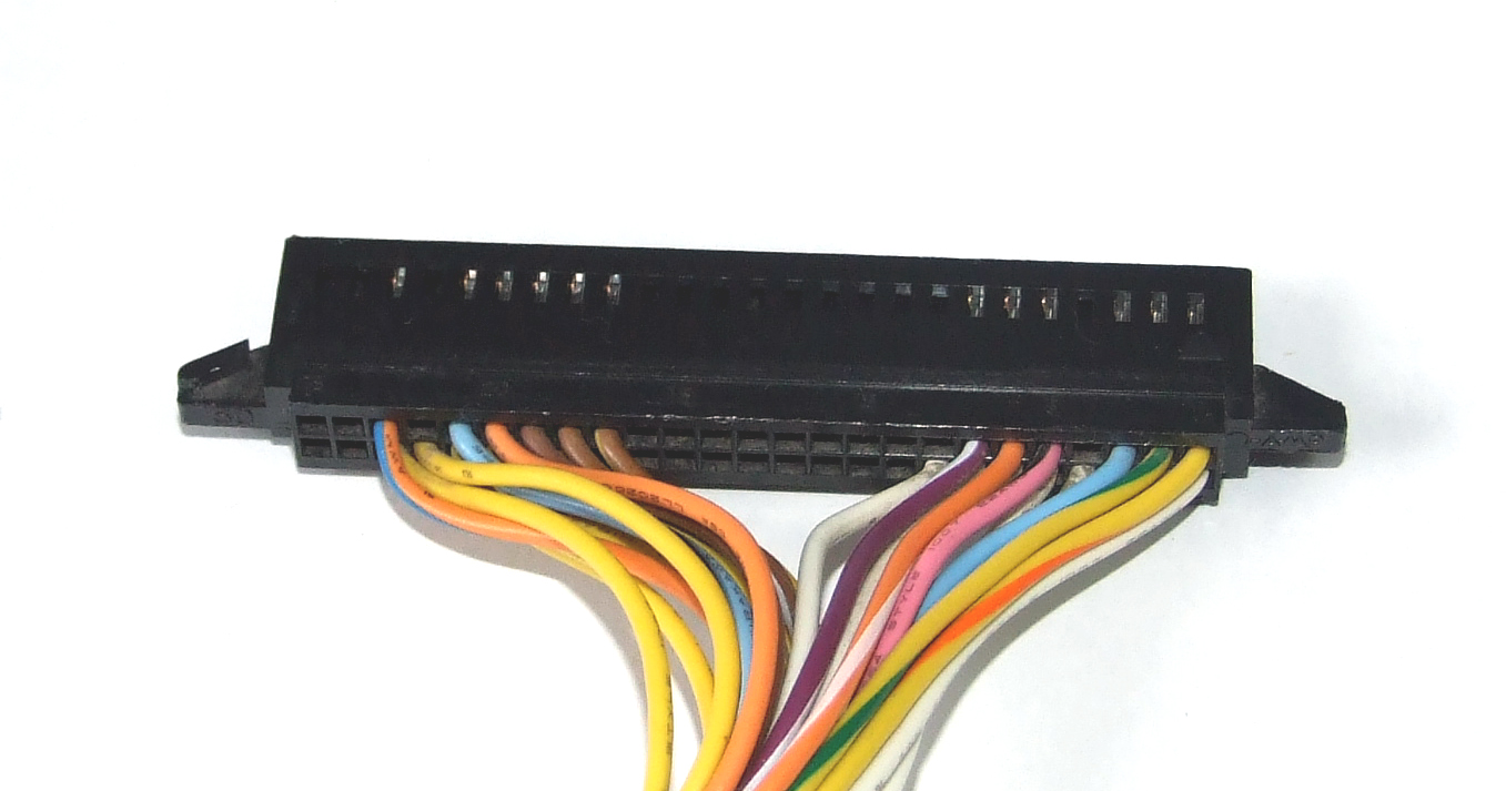
In terms on the controls, we have the steering wheel, two pedals, gear stick, coin input, start switch, and finally the test and service switches. These connect through two connectors on the board, one of which has 50 pins and the othe 20. The 20 pin connector is for the accelerator, brake and wheel. Unlike a game like Chase H.Q., the pedals and wheel are all fully analogue (Chase H.Q.'s accelerator is simply an on/off switch).
On the 50 pin connector, for the coin inputs and their ground connections I use my normal controller's coin input, since there's no button on the original control panel for it. On my PC wheel (the Thrustmaster) I was able to wire it up to one of the buttons in a straightforward fashion. You could easily connect both the test and service switches to a controller in the same way. I've connected mine to buttons 2 and 3 on the Player 1 side.
This picture shows the wiring on the inside of an original control panel. The rightmost connector is that of the start button. The four pins are for the start switch and its ground, and the start switch's lamp and its +5V connection. Obviously with my Thrustmaster controller I had no need to connect the lamp pins as there's no lamp.


The red connector on the left is for the gear stick. It has two wires, one for the switch itself and the other for its ground. So changing the gear simply tells the game that the switch has changed from one state to another. On my PC controller, the stick didn't "stick" in position, so to engage the low gear, the stick had to be held in the "up" position. Releasing the stick would engage the high gear.
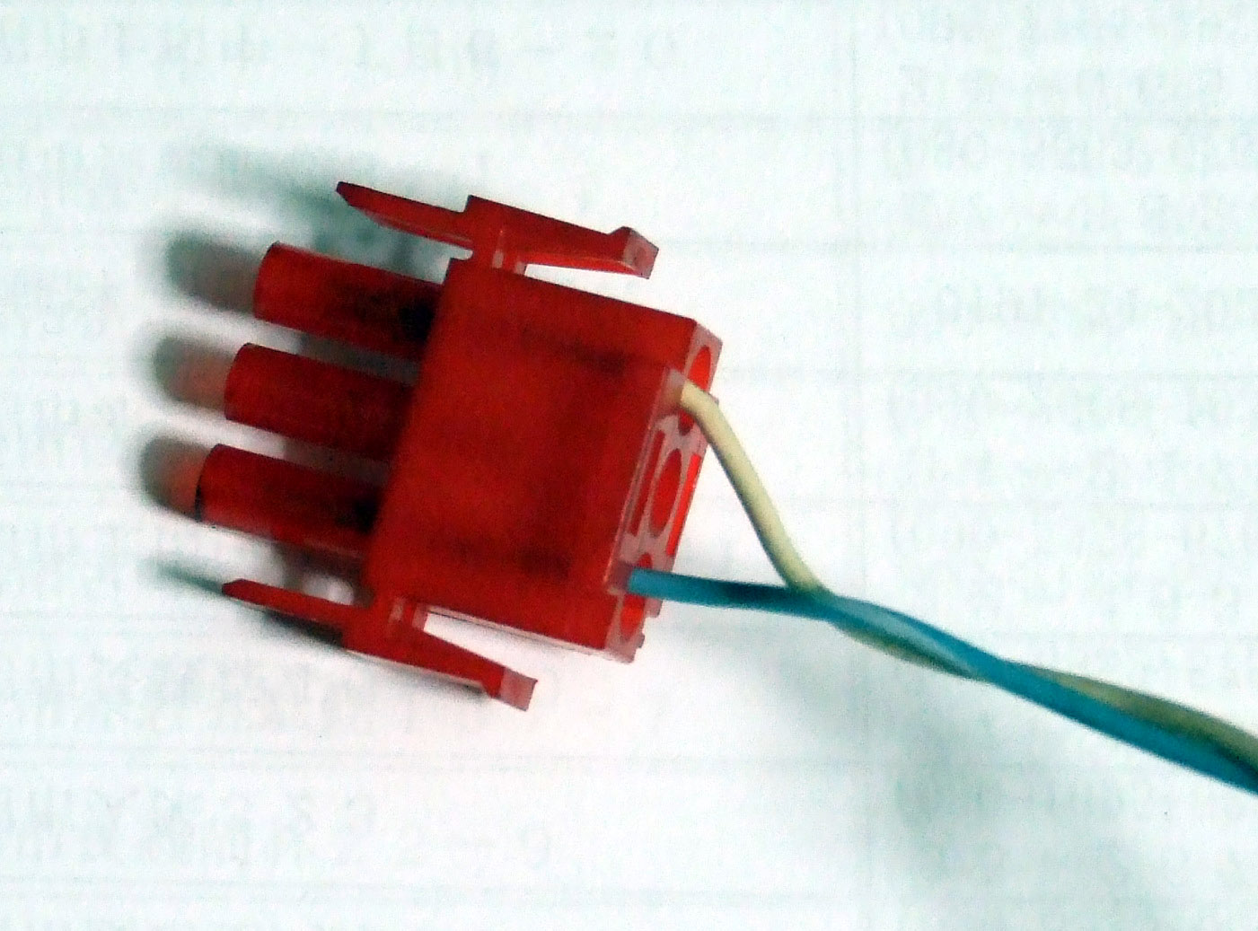
The brown connector in the centre is for the wheel itself, which has +5V, GND and a potentiometer connector. Again, on my PC wheel, this was pretty straightforward. The problem with computer and console controls is that they're usually very light and playing with them in an aggressive way (or sometimes not even in an aggressive way) will loosen up the parts. In the case of the wheel, I found that the potentiometer would gradually rotate so that the car in the game would naturally drift to the right when it should have gone straight. In order to counter this, I simply used the test mode to find the middle position and then taped down the potentiomter. Generally it stayed in position after this. With the genuine wheel I have had no such problems as would be expected.

Here's a picture of the connector for the pedals from a Power Drift cabinet. There are four pins leading to six wires. So the two pink pins go to +5V, and the two brown ones are for Ground. The two centre pins connect to the two potentiometers on the accelerator and brake.

My problem with the original pedal fixture is that I've yet to find something to attach it to (and it's very heavy), so I went back to my original PC pedals (Microsoft Sidewinder pedals). In this case I simply connected the two +5V connectors on the pot together, and likewise with the Ground connectors. Then I soldered four long wires to GND, +5V, and the two potentiometers and then terminated them with a Molex plug in the same order as the Power Drift pedals shown above. The problem with these pedals is that their range is not as great as the real pedals, so they can't reach either 0% power or 100% power. It means that when not pressing on the accelerator, the car will still move. This is not such a problem as if you really want to stop the car you'd simply step on the brake. When fully pressed down, the car will go top speed, and I have finished the game, so that's no problem. The only real problem is that on the high score screen, the game doesn't register the pedal being pushed so no names can ever be entered (this problem also exists on Hang-On)


Let's have a look now at the pinout for the 50 pins connectors. First up is Out Run.
Out Run pinout - 50 pin connector
| A1 | Coin 2 | B1 | Coins GND | |||||
| A2 | Coin 1 | B2 | ||||||
| A3 | B3 | |||||||
| A4 | Shift | B4 | Shift GND | |||||
| A5 | Start Switch | B5 | Start Switch GND | |||||
| A6 | Service | B6 | Service and Test GND | |||||
| A7 | Test | B7 | ||||||
| A8 | B8 | |||||||
| A9 | B9 | |||||||
| A10 | B10 | |||||||
| A11 | B11 | |||||||
| A12 | B12 | |||||||
| A13 | B13 | PWR AMP GND* | ||||||
| A14 | B14 | GND (from PSU) | ||||||
| A15 | B15 | GND (from PSU) | ||||||
| A16 | B16 | Coin Meter GND* | ||||||
| A17 | B17 | Coin Switches +5V* | ||||||
| A18 | DC Motor* | B18 | DC Motor* | |||||
| A19 | Coin Meter 1* | B19 | Coin Meter +5V* | |||||
| A20 | Coin Meter 2* | B20 | ||||||
| A21 | Start Lamp | B21 | Start Lamp +5V | |||||
| A22 | B22 | |||||||
| A23 | PWR AMP* | B23 | ||||||
| A24 | +5V (from PSU) | B24 | ||||||
| A25 | +5V (from PSU) | B25 | ||||||
Here's a photograph of it so you can see how it lines up. The counting starts at the right and works left. The top row is the A row, so the rightmost pin on the top is Coin 2.

I have seen pinouts for Out Run on the Internet which differ from these, so be careful. I took these pinouts from the manual and looking at my connector, they are definitely in the right positions. For instance, I've seen the +5V lines on A24 and A25 noted as being on the B side, but clearly on my connector they're not. As I say, be careful and check your own board. If you buy a harness with the board then you'll know it must be right (as long as the game was working of course).
The pins marked with an asterisk aren't needed if wiring up to a JAMMA system and you don't have coin counters etc.
The +5V lines on A24 and A25 and the Ground lines on B14 and B15 should be connected to your JAMMA harness.
On the left the three-pin connector connects to the gear stick's connector (though the middle pin isn't needed) and the four-pin connector on the right is for the Start Switch and its lamp.
Now, with Power Drift you have to be very careful. The second board I bought had a different pinout on the 20 and 50 pin connectors, the first board seems to be for an upright cabinet, and its manual is widely available on the Internet. My second board is that from a Deluxe cabinet, shown below. I've just managed to buy a copy of the manual, so I can reproduce the pinouts here.

This is the upright Power Drift's pinout below. It has slight differences to the Out Run pinout, so be careful.
| A1 | Coin 2 | B1 | Coins GND | |||
| A2 | Coin 1 | B2 | Gear GND | |||
| A3 | Gear Switch | B3 | ||||
| A4 | B4 | |||||
| A5 | Start Switch | B5 | Start Switch GND | |||
| A6 | Service | B6 | ||||
| A7 | Test | B7 | Service and Test GND | |||
| A8 | B8 | |||||
| A9 | B9 | |||||
| A10 | B10 | |||||
| A11 | B11 | |||||
| A12 | B12 | |||||
| A13 | B13 | PWR AMP GND* | ||||
| A14 | B14 | Service and Test GND | ||||
| A15 | B15 | GND (from PSU) | ||||
| A16 | B16 | GND (from PSU) | ||||
| A17 | B17 | +5V (from PSU) | ||||
| A18 | B18 | +5V (from PSU) | ||||
| A19 | Coin Meter 1* | B19 | Coin Meter +5V* | |||
| A20 | Coin Meter 2* | B20 | Coin Meter +5V* | |||
| A21 | Start Lamp | B21 | Start Lamp +5V | |||
| A22 | B22 | |||||
| A23 | PWR AMP* | B23 | ||||
| A24 | B24 | |||||
| A25 | B25 | |||||

This is the Deluxe cabinet Power Drift's pinout. As I've mentioned, I've only just found a copy of the manual so I had already made the harness without fully knowing the pinout.
| A1 | Coin 2 | B1 | GND (from PSU) | ||||
| A2 | Coin 1 | B2 | GND (from PSU) | ||||
| A3 | Gear Switch | B3 | PWR AMP GND* | ||||
| A4 | B4 | Gear GND | |||||
| A5 | Start Switch | B5 | Start Switch GND | ||||
| A6 | Service | B6 | Coins GND | ||||
| A7 | Test | B7 | Service and Test GND | ||||
| A8 | B8 | Coin Meters GND | |||||
| A9 | B9 | ||||||
| A10 | B10 | ||||||
| A11 | B11 | ||||||
| A12 | B12 | ||||||
| A13 | B13 | ||||||
| A14 | B14 | ||||||
| A15 | B15 | ||||||
| A16 | B16 | ||||||
| A17 | Coin Open* | B17 | |||||
| A18 | Coin Close* | B18 | Sub Board +5V* | ||||
| A19 | Coin Meter 1* | B19 | Start Lamp +5V | ||||
| A20 | Coin Meter 2* | B20 | +5V | ||||
| A21 | Start Lamp | B21 | +5V | ||||
| A22 | B22 | +5V (from PSU) | |||||
| A23 | PWR AMP mute | B23 | +5V (from PSU) | ||||
| A24 | B24 | ||||||
| A25 | B25 | ||||||
I've had some confusion with these Ground and +5V pins, as the wiring diagram isn't so clear. So I'll work through them on my board and see what I can confirm. It looks like pins B22 and B23 should be wired to +5V on the JAMMA harness, I have B23 connected, without it the inputs to the game won't work, and I expect B22 is the same. I tried connecting B20 to +5V and it wasn't good, reset the game and had it been connected for long looked like it was going to start smoking. So B20 and B21 look like they connect to somewhere else but I'm not sure where (network system possibly?).
Now let's move on to the 20-pin connector for the wheel and pedals. Again, first we have Out Run.
| A1 | Acc +5V | B1 | Wheel +5V | |||||||
| A2 | Acc Pot | B2 | Wheel Pot | |||||||
| A3 | Acc GND | B3 | Wheel GND | |||||||
| A4 | B4 | Brake +5V | ||||||||
| A5 | B5 | Brake Pot | ||||||||
| A6 | B6 | Brake GND | ||||||||
| A7 | B7 | |||||||||
| A8 | B8 | |||||||||
| A9 | B9 | |||||||||
| A10 | B10 | |||||||||
Here's a photograph of this connector, as you can see there are only the nine pins, and it's pretty straightforward to connect these to a PC wheel. As I mentioned earlier the two +5V and Ground wires for the pedals come from the same source, so as you can see below I use a four-pin connector on my PC pedals to easily connect to this connector. The three pin connector goes to my Power Drift panel's wheel. If I wanted to I could easily do the same with my PC wheel if I ever wanted to use that again.

Here are the 20 pin connectors for Power Drift. The upright version's pinout is completely different from that of Out Run, and the Deluxe version is again different from the other Power Drift, though it is the same as Out Run's (more or less).
Power Drift (upright version):
| A1 | B1 | ||||
| A2 | Acc Pot | B2 | Wheel Pot | ||
| A3 | B3 | ||||
| A4 | Wheel +5V | B4 | |||
| A5 | B5 | Brake Pot | |||
| A6 | Wheel GND | B6 | |||
| A7 | Acc +5V | B7 | |||
| A8 | B8 | ||||
| A9 | Acc GND | B9 | |||
| A10 | B10 | ||||

Power Drift (deluxe version):
| A1 | Acc +5V | B1 | Wheel +5V | ||
| A2 | Acc Pot | B2 | Wheel Pot | ||
| A3 | Acc GND | B3 | Wheel GND | ||
| A4 | Banking +5V | B4 | |||
| A5 | Banking Pot | B5 | Brake Pot | ||
| A6 | Banking GND | B6 | |||
| A7 | B7 | ||||
| A8 | B8 | ||||
| A9 | B9 | ||||
| A10 | B10 | ||||

A4, A5 and A6 are for the banking on a real moving cabinet and I have left them disconnected.
I also received a small extra board and its connecting cable which I left unconnected. This is for the the motor in a real cabinet.
So ultimately I've made three harnesses for these games. I have two Out Run boards with the same pinout and two Power Drift boards with differing pinouts. I've also made a harness for Hang-On, the details of which you can see here.
I've swapped EPROMs on the two Out Run boards. One of them now runs the old Japanese version, which has a different track order and some other differences. Being an earlier version, it is not quite as polished as the later releases. I've also converted my other board to the newly released updated version, for which you can get the ROMs and all relevant information from the marvellous reassembler.blogspot.com; unfortunately as my pedals won't allow me to input my initials on the high score screen, I can't make use of the new ROMs' ability to save the high scores.
Here's my Deluxe version working perfectly.

Fantastic information. Just what I need to make a loom to put a Power Drift board in an Outrun cabinet.
ReplyDeleteHowever do you know what the differences are between. the Power Drift upright and deluxe boards? They look the same, what is the number after the 834-6697 number? As this is hidden by the extenal rom board.
Also what are you after for the Suntory Tapper board?
The numbers I have on my two boards are 834-6697-11 for the upright and 834-6697-04 for the deluxe version. The upright version doesn't have the extra ROM board.
ReplyDeleteI haven't decided a price on the Tapper yet, it's very rare though so it would be quite a bit.
do u still the deluxe power drift manual and where Could I buy one
ReplyDeleteSorry I don't have it anymore, I got it from ebay originally, I suppose you could try there or the KLOV forums.
Delete